Cycle time, dimensional repeatability and scrap rate in series production depend largely on the design of the injection mold. Uneven cooling lengthens the cycle and causes warpage. A poorly placed gate shifts weld lines into mechanically loaded areas. Steel that is too soft for a glass-fiber-filled resin accelerates cavity wear. Every one of these decisions is made before the mold ever reaches the injection molding machine.
Injection Mold Construction and Choosing Between a Prototype and a Production Mold
An injection mold is a precision tool in which molten plastic takes on the final shape of the part. It consists of two main halves: the stationary half, mounted on the nozzle side of the machine, and the moving half, which retracts together with the molded part when the mold opens. The stationary side usually holds the cavity, which reproduces the external shape of the part, while the moving side carries the core, which forms the internal geometry. The part shrinks onto the core, so it stays on the ejector side when the mold opens. Injection mold construction also includes a runner system that delivers plastic to the cavities (cold runner or hot runner), a cooling system, venting and an ejector system, plus slides or collapsible cores for parts with undercuts. Once mounted in the machine, the mold receives plastic injected at high pressure, draws heat from it until it solidifies, then opens and ejects the finished part.
In practice, there are two classes of tooling. A prototype mold, made of aluminum or lower-hardness steel, is used to produce anywhere from a few hundred to a few thousand test parts. It lets you verify the part’s geometry, fit and assembly before final design decisions are made. A production mold, also called a series mold, is built from wear-resistant tool steel and designed to run hundreds of thousands or millions of cycles with consistent quality. The table below summarizes the key differences.
| Feature | Prototype mold | Production mold |
|---|---|---|
| Material | Aluminum or lower-hardness steel | Prehardened or hardened tool steel |
| Tool life | A few hundred to a few thousand cycles | Hundreds of thousands to millions of cycles |
| Cost | Lower | Higher |
| Lead time | Shorter | Longer |
| Typical use | Geometry verification, assembly trials, short test runs | Series and high-volume production |
Stages of Injection Mold Design
Injection mold design is an engineering process in which each stage sets the framework for the next. It usually follows five steps:
- Review of documentation and part geometry: the designer evaluates the 3D model of the part for moldability, looking at wall thickness, draft angles, ribs and undercuts that require slides. At this stage, features that would later cause defects or needlessly raise tooling costs are identified, and design changes to the part are proposed to the customer.
- Material selection and shrinkage analysis: the resin is usually determined by the part’s requirements and is often specified by the customer. Every material shrinks in its own way as it cools. Semi-crystalline resins (e.g., PP, PA) shrink more than amorphous ones (e.g., ABS, PS), and glass-fiber-reinforced resins shrink unevenly depending on flow direction. The designer accounts for this by enlarging the cavities with an appropriate shrinkage allowance so the finished part falls within tolerance.
- 3D mold design: the cavities are designed, the parting line (where the mold halves meet) and number of cavities are defined, and then the runner system (sprue bushing, runners, gates) is laid out along with the cooling channels, ejectors and vents.
- Flow and cooling simulations: CAE software (such as Autodesk Moldflow or Moldex3D) fills the mold virtually to show how the plastic will flow through the cavities, where weld lines will form and whether cooling is uniform.
- Design validation: the design goes to the toolroom only after the simulation results have been reviewed and all tolerances and quality requirements have been agreed with the customer.
Injection Mold Steel and Part Material Selection
Injection mold steel is selected primarily based on the expected number of cycles and the type of resin being processed. For short and medium runs, prehardened steels supplied in a pre-toughened condition (e.g., 1.2311 or 1.2738) are used, which are machined without subsequent hardening. Tooling for high-volume production, especially with abrasive glass-fiber-reinforced resins, is made from hardened steels (e.g., 1.2343), while materials that release corrosive compounds during processing, such as PVC, call for stainless steels (e.g., 1.2083). Mold base plates that never contact the plastic are usually made from less expensive unalloyed steels.
At the same time, the part material itself shapes the cavity design. Data sheet values, including molding shrinkage, are determined on standardized test specimens molded according to the ISO 294 series of standards. The general principles are set out in ISO 294-1, which covers injection molding of test specimens of thermoplastic materials. This makes values from different resin suppliers comparable. Keep in mind, however, that these are reference values. Actual shrinkage in a part depends on wall thickness, gate location and process parameters, which is why an experienced toolroom verifies them against its own data.
For automotive plastics, where stricter dimensional and strength requirements apply, the choice of steel and resin pairing translates directly into tighter cavity tolerances and the durability of the molding surfaces.
Mold Filling and Cooling Simulations
Computer simulations let you „see” the injection process before a single mold component is made. Flow analysis shows where sink marks, weld lines, air traps or warpage caused by uneven cooling may occur. The design can then be corrected while the change still affects only the model, before any steel has been machined. In a peer-reviewed study on CAE simulations in injection molding, the authors compared Moldflow results with the actual process for a part used in electromechanical devices. Maximum deviations were about 3–5% for pressures and clamping force and 1.5% for shrinkage. With this level of accuracy, simulation has become a standard project stage in toolrooms, since it costs far less than correcting a finished tool.
Injection Mold Manufacturing: From Steel Block to Finished Tool
Once the design is approved, the tooling stage begins, and injection mold manufacturing demands the highest precision. Steel blocks go onto CNC machines, where roughing gives the cavities and plates their initial shape. Hardened steel components then undergo heat treatment, followed by finishing operations such as high-speed milling and grinding. Complex geometries, sharp internal corners and deep, narrow ribs are produced by electrical discharge machining (EDM), which reproduces the shape of an electrode where a cutter cannot reach. Finally, standard components such as guide pillars, ejector pins and hot runner elements are installed, and the mold is assembled.
The next step is trials. During the T0 trial, the mold goes onto the injection molding machine for the first time, and the designer and process engineer evaluate the first shots: cavity fill, surface quality and dimensions. Based on these results, the cavities are corrected and further trials are run (T1, T2…) until the part meets all requirements. Once the dimensions are approved, the molding surfaces are polished or textured to the required finish class.
How Does Plastic Injection Molding Work in a Molding Plant?
The finished mold starts its real work on the production floor. A plastic injection molding cycle consists of several repeating phases:
- Mold closing: the mold halves come together and are clamped with a force that must exceed the separating force of the plastic in the cavity.
- Injection: molten plastic is forced into the closed mold at high pressure and fills the cavities.
- Packing: sustained pressure compensates for the volume loss of the plastic cooling in the cavity and prevents sink marks.
- Cooling and plasticizing: the part solidifies as it transfers heat to the mold’s cooling system; this phase usually takes up the largest share of the cycle. Meanwhile, the rotating screw melts pellets in the heated barrel and prepares the shot for the next injection.
- Mold opening and ejection: once the part has solidified, the mold opens and the ejectors push out the finished part, after which the cycle starts again.
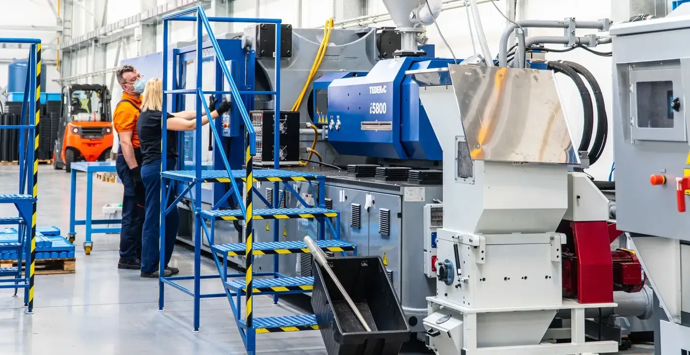
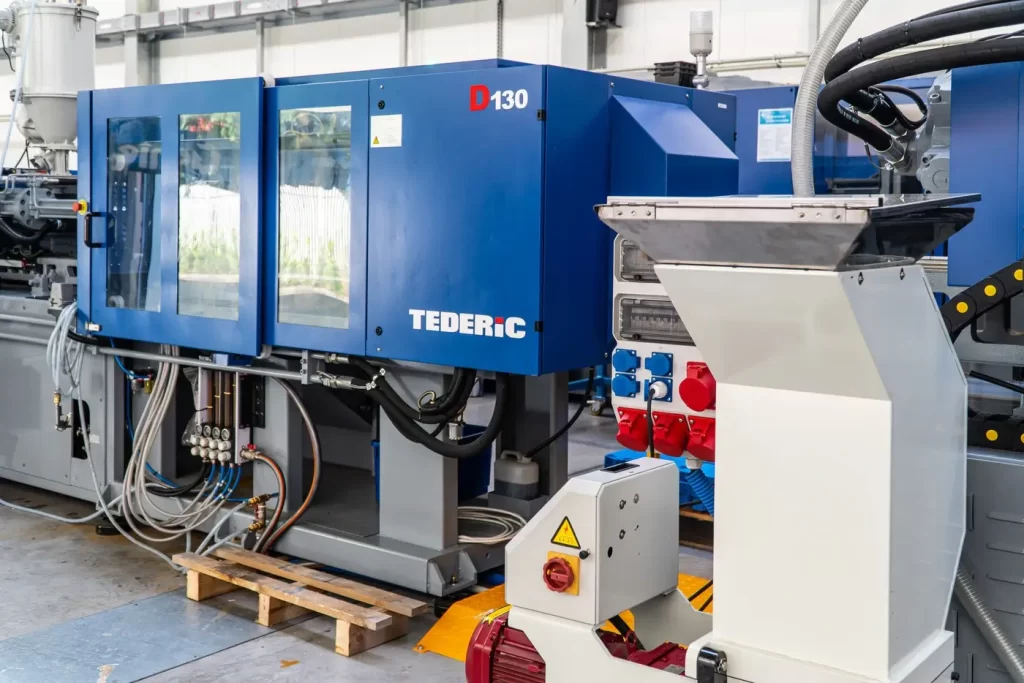
Matching a machine to a mold depends mainly on the required clamping force, which is determined by the projected area of the part and the cavity pressure, as well as on shot volume and the dimensions of the mold itself. The mold must fit between the machine’s tie bars and within its mold height range. That is why molding plants maintain a fleet of machines in a range of tonnages. The Strumet injection molding plant operates Tederic machines with clamping forces from 130 to 700 tons, and the largest of them can inject about 3.4 kg of plastic in a single shot.
Injection Mold Applications in Automotive and Industry
The largest share of injection molded parts goes to the automotive sector. Automotive plastics are used to make housing components, vehicle interior parts, clips and fasteners, as well as parts that mate with metal assemblies, where precise fit determines smooth installation on the line. Beyond automotive, plastic injection molds serve the household appliance, electrical, agricultural and packaging industries, along with any sector where repeatability across large runs matters.
A full-service supplier has the advantage of combining injection molding with other processes under one roof. A plastic part is often just one component of a larger assembly that also requires metalworking, welding or corrosion protection. In a full-service industrial contract manufacturing model, the molded part, the metal structure and, if needed, polyurethane castings are all produced by a single partner, which shortens the supply chain.
How Much Does an Injection Mold Cost and How Do You Choose a Mold Maker?
The price of an injection mold and its lead time cannot be reduced to a single number. They depend on several interrelated factors:
- Part complexity: undercuts, slides, thin walls and tight dimensional requirements increase the toolroom workload.
- Number of cavities: a multi-cavity mold is more expensive and more complex, but at high volumes it significantly lowers the unit cost of the part.
- Runner system: a hot runner raises the tool price but reduces runner waste and often shortens the cycle.
- Type of resin: abrasive, corrosive or high-temperature materials require more expensive steels and finishes.
- Production volume: the expected number of cycles determines the tool class (prototype or production).
When choosing a contract partner, look beyond the price of the tool alone. What matters: an in-house fleet of injection molding machines, so production starts with the same supplier right after trials; experience in design and simulation; toolroom capacity for ongoing corrections and mold maintenance; measurement capabilities to verify molded parts; and the quality certifications required in automotive. Having all of these capabilities in one place shortens the path from drawing to repeatable production and reduces the risk of costly rework.
Your contract with the mold maker should specify who owns the mold and who is responsible for its inspections, storage and any transfer to another facility.
Planning to launch production of a new part or looking for a partner for series production? Describe your project and send a request for quote to the Strumet injection molding plant. We will analyze your part and propose an injection molding process tailored to the requirements of your industry.
FAQ: Common Questions About Injection Molds
How much does it cost to make an injection mold?
The cost depends on part complexity, number of cavities, runner system type, resin and expected production volume, so it is quoted individually based on the documentation. A simple single-cavity mold is much less expensive than a multi-cavity production tool, which in turn lowers the cost of each individual part.
How long does it take to design and build an injection mold?
In practice, anywhere from a few weeks to a few months. This time covers design and simulation, toolroom machining and T0/T1 trials with corrections. The more complex the geometry and the higher the requirements, the longer the lead time.
What is the difference between a single-cavity and a multi-cavity injection mold?
A single-cavity mold produces one part per cycle and is less expensive to build, while a multi-cavity mold produces several or even dozens of parts at once. The latter is chosen for high volumes because, despite the higher tooling cost, it significantly lowers the unit cost.
How does a cold runner mold differ from a hot runner mold?
In a cold runner mold, the plastic in the runners solidifies along with the part and is removed as a runner, which has to be separated or reground. In a hot runner mold, the runners are heated, so the plastic stays molten until the next shot. This type of mold is more expensive, but it reduces waste and makes production easier to automate.
What steel are injection molds made from?
Most often from prehardened tool steels (e.g., 1.2311, 1.2738) or hardened tool steels (e.g., 1.2343), selected for tool life and the type of resin. For high-volume runs and abrasive resins, such as glass-fiber-filled grades, steels with increased wear resistance are used, and for corrosive resins such as PVC, stainless steels.
How many cycles can an injection mold run before it needs to be replaced or repaired?
A well-designed, regularly maintained production mold made of hardened steel can run hundreds of thousands or even millions of cycles. Its service life depends on the mold material, the type of resin being molded and how regularly the tool is inspected and maintained.